In process dynamics and control, understanding errors in systems like air conditioners (ACs), washing machine etc helps chemical engineering students learn how to manage industrial processes.
In process dynamics and control, we deal with responsiveness of output result to change in some input variables (manipulated variables) while keeping some input constant (controlled variables) throughout whole process. There are many methods to achieve desired output. And one of the prominent method we use is, error determination by taking difference in two sample point of input variables over time and continue process until unless we get error equal to zero.
Besides of this, we have also another motive to study this subject such as eliminating offset, removing sluggishness, and performing stabilising action to reduce oscillation.
You may notice some codes on AC systems (e.g., E1, E4, F1) when something goes wrong, such as a sensor failure or pressure issue. Isn't it? These codes reflect errors that disrupt the system’s ability to maintain the desired temperature (setpoint).
In this article, I will discuss:
1. What is Error in a process control?
2. Regulatory vs Servo Problems
3. Selected AC error code : analysis and solution
E1 : Indoor or Outdoor Unit Sensor Fault
E4 : High Pressure Protection
F1 : Refrigerant Leakage or Low Refrigerant Levels
F3 : Indoor or Outdoor Fan Error
U1 : Voltage Drop Error
PO : Inverter Drive Malfunction
4. Why is this important for Chemical Engineering?
1. What is Error in a process control?
There are various definition of error which you may have studied. Their definition change as you switch to another subject.
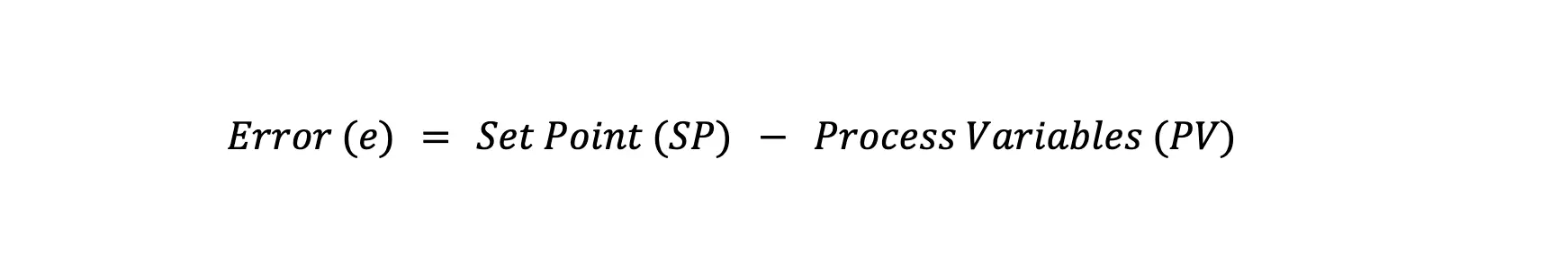
In term of process control, can you define error? Well, we can define the error as a difference between the setpoint (desired temperature, e.g., 22°C) and the process variable (actual room temperature). While defining error, two new terminology is introduced : (a) Set Point and (b) Process Variables
Mathematically, we can write error such that :
For example, if the setpoint is 22°C and the room is 25°C:
 This value (-3°C) show that system need to decrease temperature of environment by 3°C to achieve set point.
Error codes like E1 or F1 indicate specific faults causing this error, connecting to sensors, pressure, or communication issues. Below, we will explore error codes, their causes, and how to address them in the context of process control.
2. Regulatory vs. Servo Problems
Before starting discussion of different types of error, its important to know the difference between regulatory and servo problems in control systems:
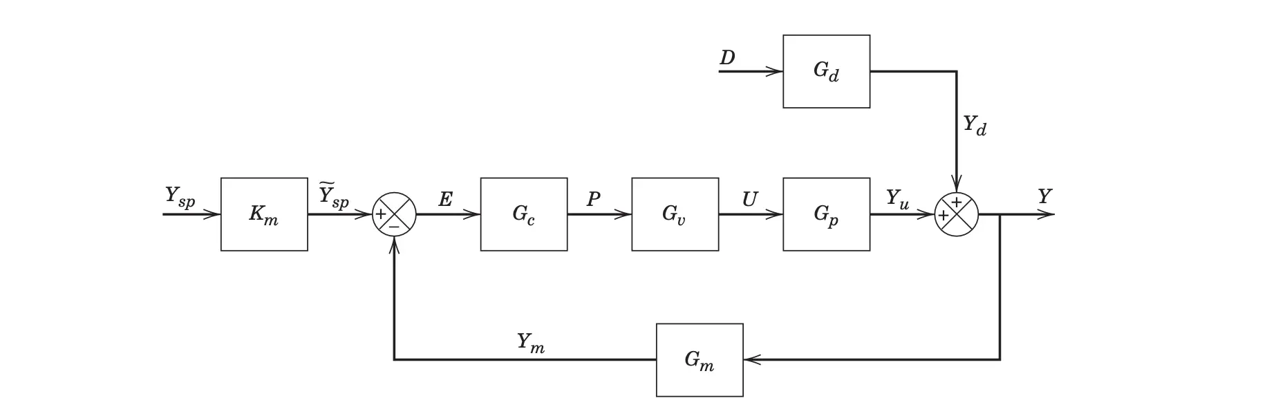
- Regulatory Problem: The system maintains the process variable (e.g., room temperature) at a fixed setpoint despite external disturbances (e.g., high pressure, heat load). The goal is to reject disturbances and keep the system stable.

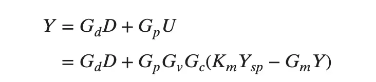
For regulatory problem with constant set-point (Deviation variable, Ysp = 0) :

- Servo Problem: The system adjusts the process variable to follow a changing setpoint (e.g., changing the desired temperature from 22°C to 18°C). The goal is to track the setpoint accurately.
In this case, we assume no disturbance change occurs and thus D=0 
3. Selected AC Error Codes: Analysis and Solutions
I’ll discuss a subset of error codes (E1, E4, F1, F3, H6, P0, U1) to illustrate different types of faults, their impact on control with mathematical perspective, and also focusing on solutions.
3.1 E1: Indoor or Outdoor Unit Sensor Fault
In a control loop, the sensor provides value of the PV (process variables) to the controller. Error E1 Indicates a faulty temperature sensor in the indoor or outdoor unit, leading to incorrect temperature readings (PV) and hence causing incorrect control actions. Regular sensor calibration ensures the error calculation is accurate.
If the sensor misreads the room temperature as 20°C instead of 25°C when the setpoint is 22°C, the error is miscalculated:
e = 22°C - 20°C = +2°C (instead of 22°C - 25°C = -3°C)
This causes the AC to reduce cooling, leading to poor temperature control.
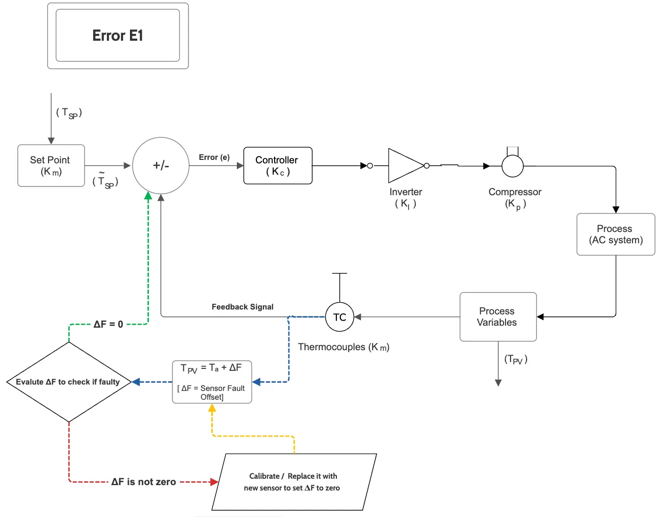
Suppose, in this case, sensor reads 20°C instead of 25°C and set point (Tsp) is 22°C , such that :
ΔF = 20°C - 25°C = -5°C
e = Tsp−Tpv=Tsp−(Ta+ΔF)
For steady-state offset (e=0),
Ta = Tsp - ΔF = 22°C -(-5°C) = 27°C (room stabilises at 27°C)
Solution to this error include :
- Calibrate or replace the sensor to ensure accurate PV measurement.
- Clean the sensor to remove dust or any obstacles.
- Check wiring connections to the sensor.
3.2 E4: High-Pressure Protection
Error E4 indicates excessive pressure in the refrigerant system which may stop the compressor, often triggering the AC to shut down and stop cooling for safety.
If the room temperature rises to 27°C (PV) with a setpoint of 22°C:
e = 22°C - 27°C = -5°C
The controller cannot reduce this error because the system is in protection mode, failing to regulate against the pressure disturbance.
If T increases due to a blocked condenser (a disturbance), P will rises (according to ideal gas law), triggering E4. if T rises from 300 K to 320 K with constant n and V:

This 6.7% pressure increase may exceed the system’s safe limit, causing shutdown.
High pressure acts as a disturbance variables, forcing the system into a protective state. Hence, this becomes case of regulatory problem rather than servo. A well-tuned controller can detect rising pressure early and reduce compressor speed to avoid shutdown.
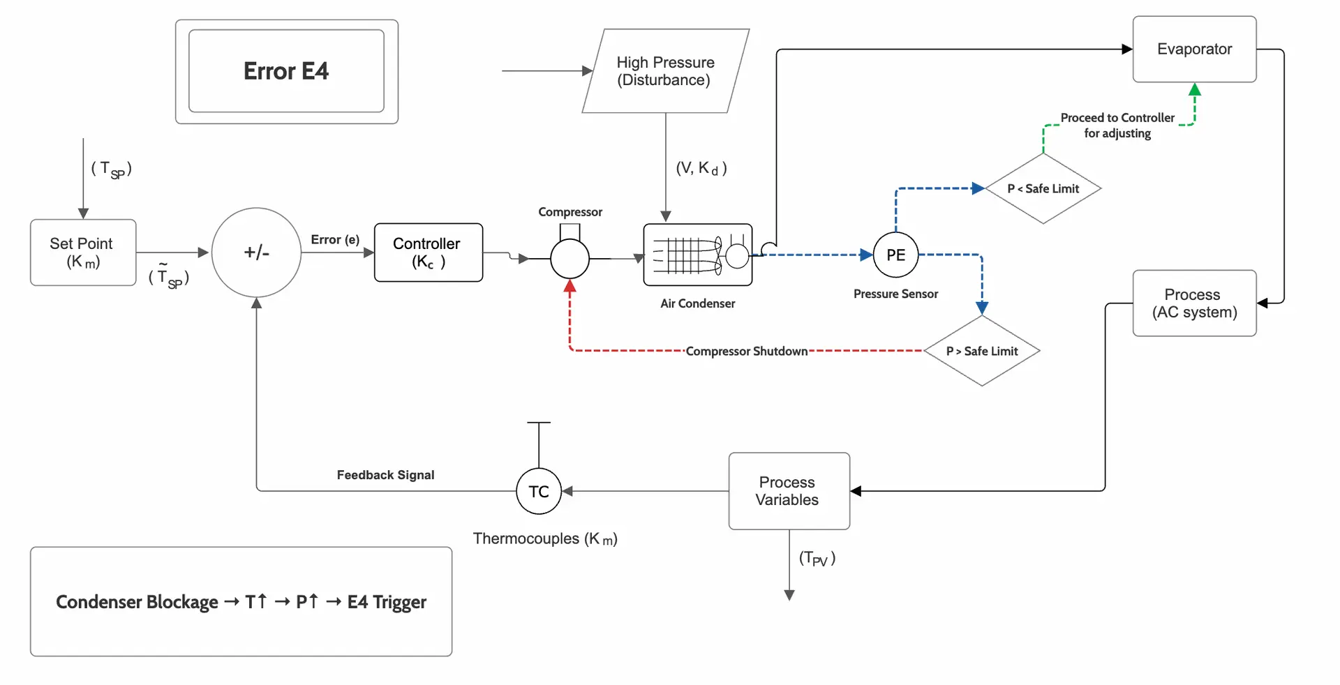
The control output (u) for a PID controller is:

If pressure sensors detect rising P, the controller can reduce u to slow the compressor, mitigating the disturbance before E4 triggering.
Solution to this error include :
- Clean condenser coils to improve heat transfer, reducing T.
- Install a pressure relief valve to manage high-pressure spikes.
- Use a controller with adaptive tuning to reduce compressor speed (u) before pressure becomes critical.
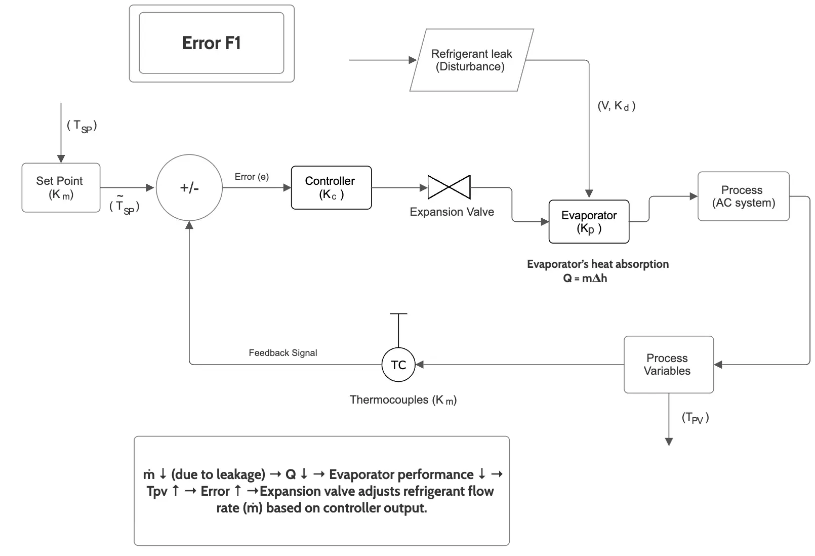
3.3 F1: Refrigerant Leakage or Low Refrigerant Levels
Error F1 indicates low refrigerant levels, reducing the AC’s cooling capacity, so causing the room temperature to stay above the setpoint. The error persists (formation of offset) because the system cannot transfer enough heat.
Cooling capacity (Q) depends on refrigerant flow rate (ṁ) and specific enthalpy change (Δh) such that:

Low refrigerant is a system disturbance that reduces the process gain (cooling effect per control effort). A controller with integral action can compensate temporarily, responsible for eliminating offset but cannot fix the root cause.
Solution to this error include:
- repair leaks using a leak detector.
- Recharge the system with the required amount of refrigerant.
- Schedule regular maintenance to check refrigerant levels
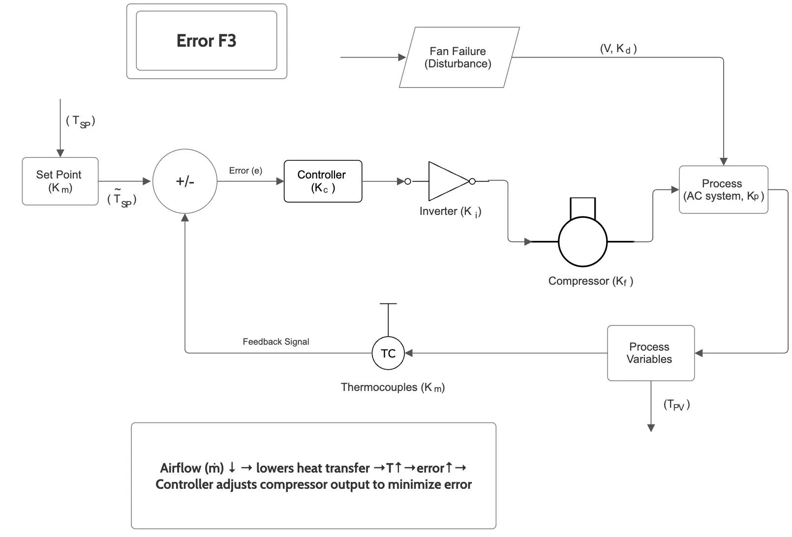
3.4 F3: Indoor or Outdoor Fan Error
Error F3 indicates a problem with the indoor or outdoor fan, reducing airflow and heat transfer. Poor airflow increases the room temperature, hence giving rise to error in temperature due to stopped fan.
Heat transfer (Q) depends on airflow rate (ṁ) and temperature difference (ΔT) such that:

Fan errors reduce the system’s ability to respond to control actions. A controller may increase compressor speed to compensate.
Solution to this error include:
- Repair or replace the fan motor.
- Clear obstructions from fan blades.
- Check electrical connections and fuses.
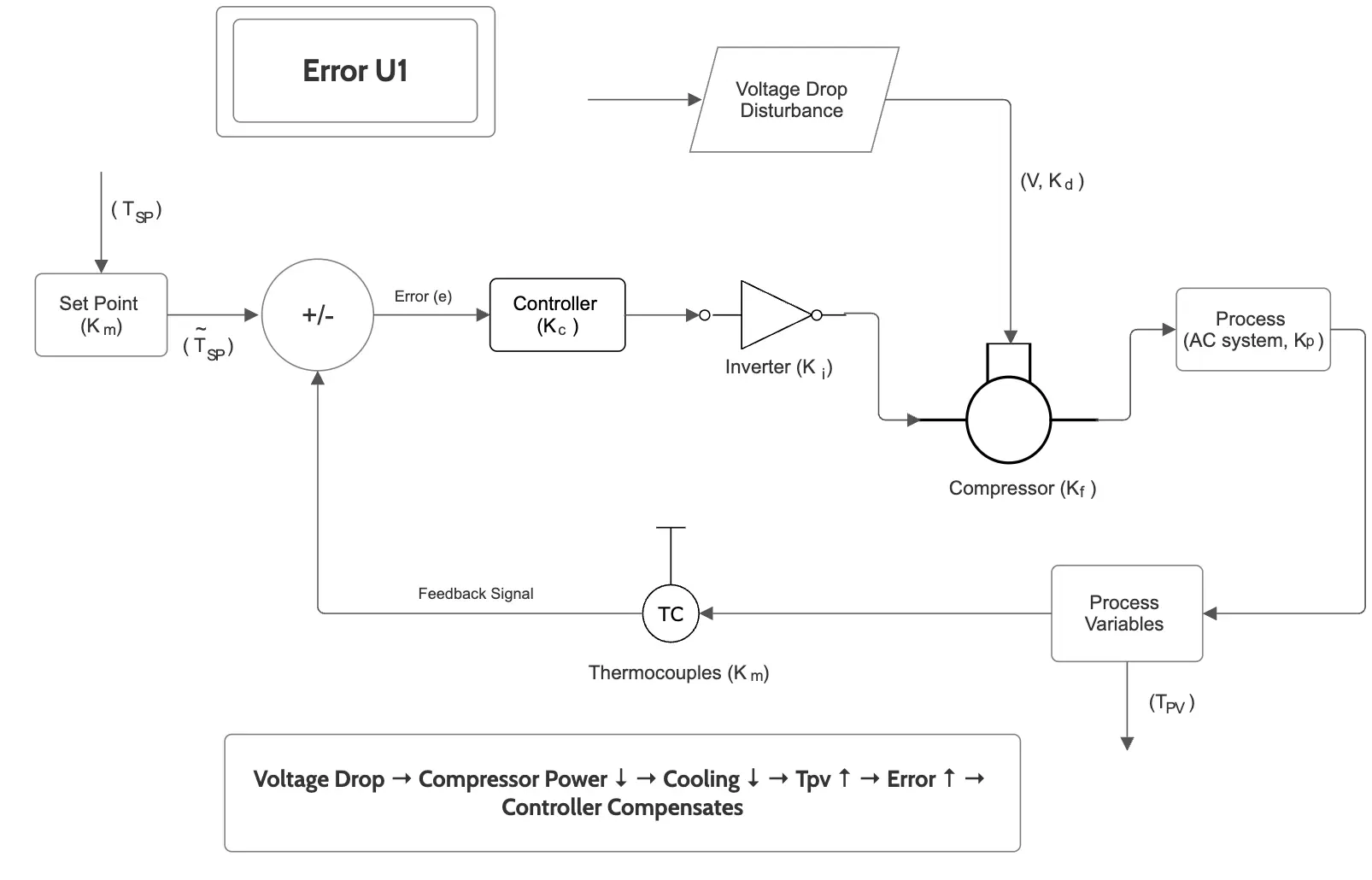
3.5 U1: Voltage Drop Error
Error U1 indicates a voltage drop, reducing system efficiency (compressor and fan efficiency). Power (P) to the compressor depends on voltage (V) such that :
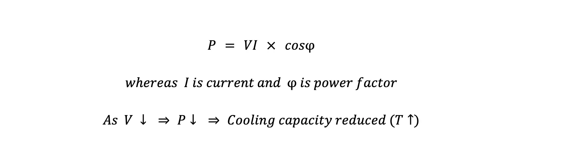
Here, voltage drops act as external disturbances (regulatory problem), reducing system performance, hence requiring external power solution or effective controller to adjust voltage.
Solution to error include:
- Use a voltage stabiliser to maintain consistent power supply.
- Check and secure electrical connections.
- Install a backup power system for critical applications.
3.6 P0: Inverter Drive Malfunction
Error P0 indicate a problem with the AC’s inverter. The inverter is part of the actuator (final control element) in the control loop, responsible for compressor speed. A malfunction reduces the controller’s ability to manipulate the process variable, requiring hardware repair.
A faulty inverter may lock the compressor at a fixed speed or stop it, preventing error correction. Compressor power (P) depends on inverter frequency (f). If the inverter fails, f becomes fixed or zero, limiting control.
Solution to this error include:
- Replace the inverter board if damaged.
- Install surge protectors to prevent electrical damage.
- reset inverter software.
4. Why is This Important for Chemical Engineers?
These AC error codes give you an idea about real-world control system challenges relevant to chemical engineering. For example:
- Sensor errors (E1) are like faulty thermocouples in a reactor, leading to incorrect temperature control.
- Pressure errors (E4, P1) resemble pressure issues in distillation columns, requiring safety mechanisms.
- Refrigerant leaks (F1) are analogous to material losses in chemical processes, reducing efficiency.
Understanding these errors helps students design better control systems for industrial processes, ensuring stability and efficiency.
Application of PDC Part-1